PARALOID B-72 AS A STRUCTURAL ADHESIVE AND AS A BARRIER WITHIN STRUCTURAL ADHESIVE BONDS: EVALUATIONS OF STRENGTH AND REVERSIBILITYJERRY PODANY, KATHLEEN M. GARLAND, WILLIAM R. FREEMAN, & JOE ROGERS
4 TENSILE TESTSTensile evaluations were based upon the standard ASTM D2095 (Skeist 1977; Pocius 1997) but modified sufficiently to accommodate a marble substrate and assure strict alignment of the samples for accurate results and minimal deviations. It was decided that a common epoxy and polyester adhesive would be compared to both a commercially available B-72 adhesive (HMG brand) and B-72 in a high solids solution, often used as an adhesive for ceramics (Koob 1986). Joints prepared with a B-72 barrier and a structural adhesive were also tested. Acetone and toluene were used for the B-72 high solids solutions (used as an adhesive) and for the lower percentage barrier coatings. While other solvents are used in the application of B-72, such as methyl ethyl ketone, it was felt that acetone and toluene represented the most common and appropriate ranges of volatility and solvent action. Toluene provided a reasonable comparison to acetone, clearly reflecting the different effects the two solvents have on the polymer chain (Hansen 1994), the absorption of the polymer solution into the substrate, and the differing rates of solvent loss after application. 4.1 ADHESIVES TESTEDSeven samples of each of the following adhesive groups were prepared at the J. Paul Getty Museum:
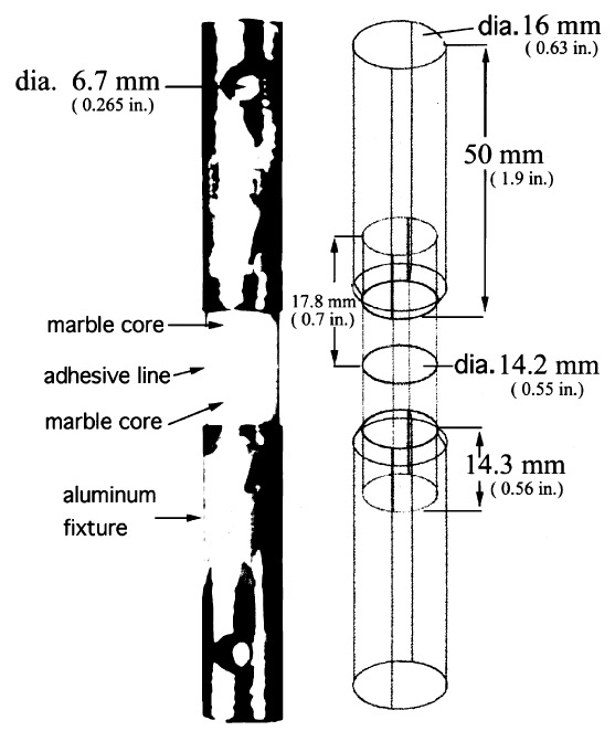
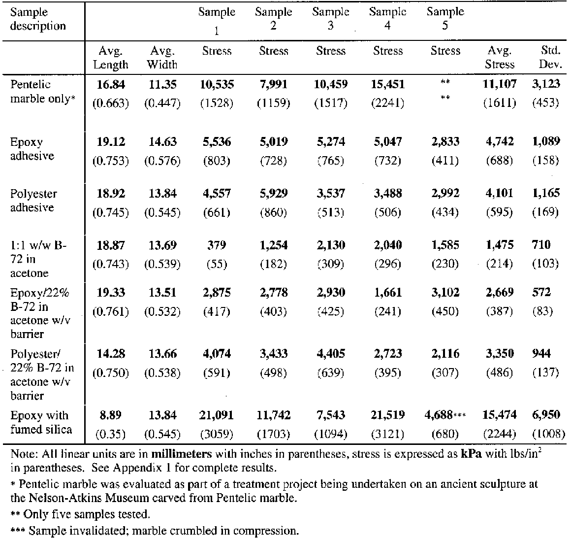
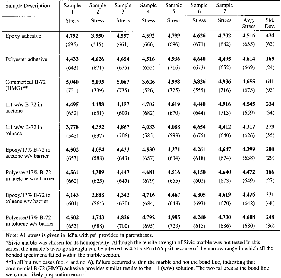
4.2 SAMPLE PREPARATIONThe test specimens were prepared as follows: one end of each marble core was adhered into one end of an aluminum holding fixture. The exposed ends of the marble cores were joined together with a range of adhesive types to produce sets of test coupons shown in figure 5. One hundred and twenty-six aluminum holders were prepared by drilling a single hole into one end of an aluminum rod (see fig. 5 for dimensions). At the opposite end of the aluminum holders, a small-diameter hole was drilled at right angles to the central axis. These were used for securing the coupon in the testing apparatus. Marble cores, 14.2 mm (0.55 in.) in diameter and 17.8 mm (0.7 in.) long, were drilled from a single slab of Sivic marble, which was selected because it is a medium-grain white marble from Yugoslavia that is highly consistent and free of inclusion planes, vugs, and voids (Walker Zanger 1999). An average tensile strength for Sivic marble of 4,520 kPa (655 psi) can be inferred by the results reported in table 3. Both ends of each marble core were ground flat and 90� to the central axis and finished with a 220 grit wetsanding. The cores were placed in an ultrasonic water bath and rinsed with deionized water followed by an acetone rinse to ensure the removal of any surface contaminant. The first step in preparation of the actual test coupons was to adhere a marble core into one of the two aluminum holding fixtures using Araldite AY 103 with HY 991 hardener. Approximately 50-60 mg of adhesive was applied to the bottom of each fixture end hole to assure a thin and consistent bond line with minimum squeeze-out onto the edges of the core. The core was fully seated in the flatbottomed hole, leaving approximately one-half of the core length exposed. Alignment of the core with the central axis of the aluminum holder was critical and was assured before the bond was allowed to cure at room temperature. Once the first half of the test coupon was prepared, a matching core was bonded to the already seated core using one of the nine different adhesive types to be tested. The application of the adhesive on all the core-to-core bonds utilized a relatively consistent 20 mg of adhesive. The adhesive was dropped in the center area of one side of the joint. The other core was then brought into contact with the first and gently moved in a circular, as well as back-and-forth, motion to assure an even distribution of the adhesive. Firm downward hand-pressure was then applied to assure the squeeze-out of any excess adhesive and the creation of a thin, consistent bond line. Excess adhesive was gently removed with a dry swab, and the sample was aligned and allowed to set in an ambient environment of 21�C (70�F) (+/− 5�) and an RH of 55% (+/− 5%). The sample was supported in the vertical position for 24 hours to assure a reasonable set of the adhesive bond. Following that 24-hour period, the second aluminum holding fixture was adhered to the assembly in the manner described above. True axial alignment of the four parts was assured by rolling the assembled test coupon on a horizontal steel bed that had been milled flat. If the coupon was in full contact with the
When the B-72 was to serve as a barrier layer between the substrates and the structural adhesive, a single coat of 17% w/v B-72 in acetone or toluene was applied to the substrate by four brush strokes using a soft 6 mm (0.25 in.) natural bristle brush, each stroke originating from the central point of the core surface and one final stroke to even any edge buildup. The barriers were allowed to dry for two weeks prior to bonding of the cores. All adhesive bonds were allowed to cure or air-dry for three weeks prior to testing. 4.3 BOND LINE EVALUATIONS FOR TENSILE TESTINGTwo assemblies of each of the adhesive groups, consisting only of bonded marble cores, were prepared at the same time in an identical manner. After curing, these core sets were cut in half along the axial direction and the cut surface was polished. Each set was examined to determine bond characteristics, specifically the dimension of the adhesive line.
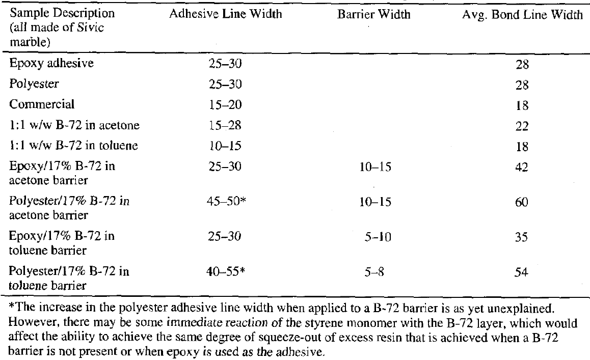
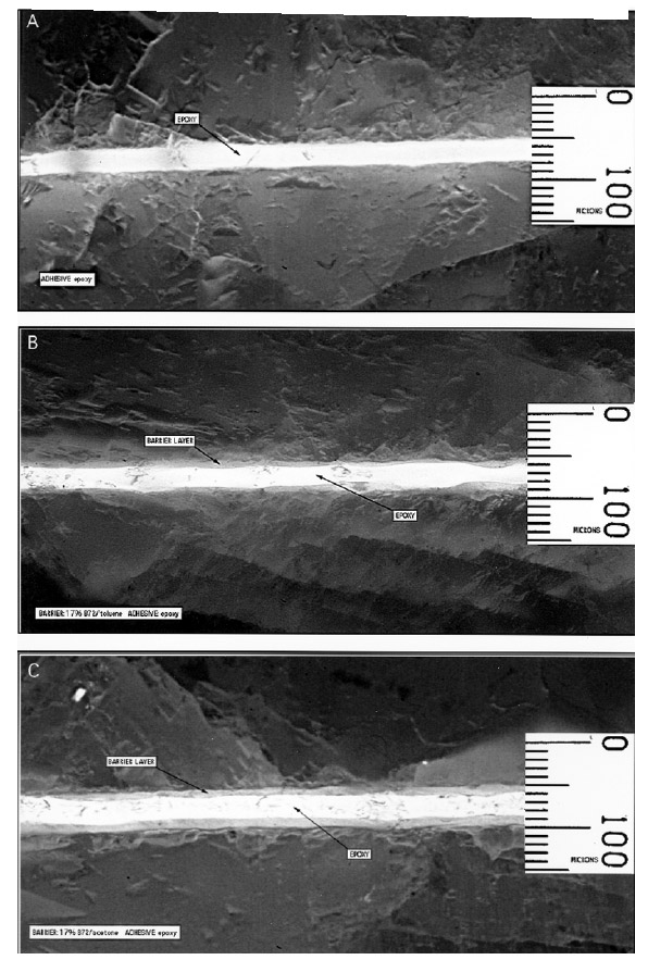
Examination of the sectioned bonds using UV microscopy revealed a relatively consistent bond line across the length of the joint, consistency between pairs of sectioned samples, and consistency between similar groups. For example, the epoxy bond line thickness was approximately the same whether the epoxy was used alone or with a barrier film, 25-30 �m. The average bond lines for the groups are listed in table 1.Figure 6 clearly shows that the difference in the barrier thickness achieved was somewhat dependent upon the solvent used to prepare the 17% w/v solution. The barrier thickness of the B-72–toluene mixture is less than the B-72–acetone mixture, most probably because the toluene mixture has greater “flow” under pressure and before drying. Because of this the squeeze-out from the joint is
|
